


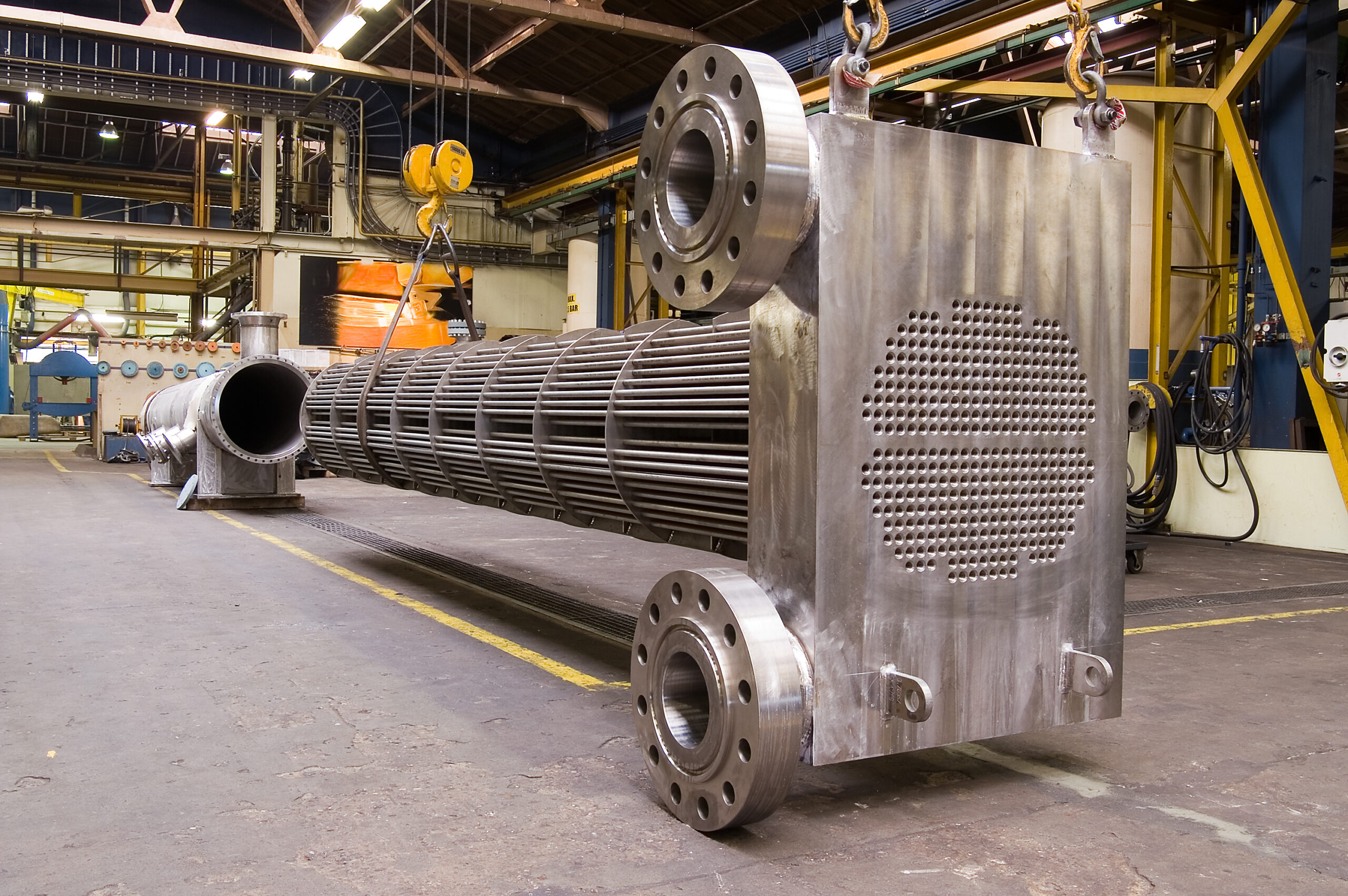
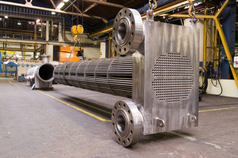
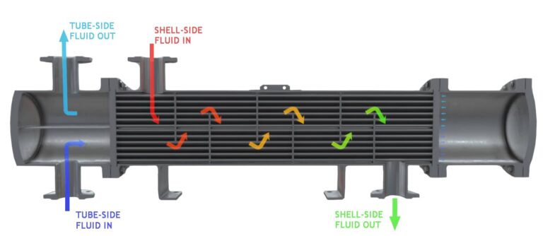
Shell and Tube Type Heat Exchanger
- Shell and Tube Heat Exchangers are widely used due to their Rigid construction and Long Life.
- We manufacture Shell and Tube for Hydraulic Oil Cooling, Lubrication Oil Cooling, Gearbox Oil Cooling, Transformer Oil Cooling, Process water cooling etc.
- Simplex and Duplex Oil coolers for Lubrication.
- Our designs are as per ASME Sec VIII and TEMA Standards.
- Our Thermal and Mechanical Design Engineers constantly thrive to achieve optimum design All the designs are strictly as per design Standards.
- Boiler Quality material such as SA 516 Gr.60/70 is used as per customer request.
- Hydro and Eddy current Tested Tubes are used for Shell and Tube Heat Exchanger manufacturing.
- Tubes are usually of Copper, Admiralty Brass, SS 316, Cupro-Nickel etc as per service requirements.

Thermal parameters are taken into account by HMI while designing any Shell and Tube Type Heat Exchanger –
The thermal design of a shell and tube exchanger is an iterative process that is normally carried out using computer programs or excel programs developed in-house by HMI. In order to calculate the heat transfer coefficients and pressure drops, initial decisions must be made on the sides the fluids are allocated, the front and rear header type, shell type, baffle type, tube diameter, and tube layout. The tube length, shell diameter, baffle pitch, and a number of tube passes are also selected and these are normally the main items that are altered during each iteration in order to maximize the overall heat transfer within specified allowable pressure drops.
The main steps in the calculation are given below:
1. Calculate the shell side flow distribution
2. Calculate the shell side heat transfer coefficient
3. Calculate tube side heat transfer coefficient
4. Calculate tube side pressure drop
5. Calculate wall resistance and overall heat transfer coefficient
6. Calculate the mean temperature difference
7. Calculate the area required.
8. Compare area required with the area of assumed geometry and allowed tube side and shell side
pressure drop with calculated values.
9. Adjust assumed geometry and repeat calculations until Area required is achieved within the
allowable pressure drops.
Material of Construction –
| General Application | Special Application | |
| Shell | M.S (ERW Pipe) | S.S (Seamless Pipe) |
| Tubes | Copper | CuNi 70:30 /CuNi 90:10 |
| Tube-sheets | M.S | Ab-2, SS, Naval Brass |
| End Covers | Cast Iron | LG-4, Gun Metal, SS |
| Baffles & Tie Rods | M.S | S.S , Brass |
Benefits of Shell and Tube Heat Exchangers
Cost
An important benefit of shell and tube heat exchangers is their cost. They are much less expensive than plate-type coolers.
Heat Capacity
Heat exchangers have to be able to handle a wide range of temperatures, varying by application. Their ability to deal with extreme temperatures helps maintain production and keep operations moving. Shell and tube heat exchangers have a high-temperature working capacity and can be adapted to fit any conditions.
Pressure
High pressure creates major problems and leads to a loss of production. The shell and tubes of shell and tube heat exchangers are tested and designed to withstand extreme pressure variances.
Pressure Loss
Pressure loss is a loss of energy and causes downstream pressure loss that slows the velocity of flow. Shell and tube heat exchangers are designed to deal with pressure loss and keep it to a minimum. There are several variables that are affected by pressure loss, one of them being the fouling of the shell and tubes. With the minimal pressure loss allowed by shell and tube heat exchangers, this problem is eliminated.
Anodes
Sacrificial anodes in the end covers of a shell and tube heat exchanger create a protective film on the surface to prevent corrosion. The purpose of the anodes is to extend the life of heat exchanger parts through the application of cathodic protection. The anodes are installed on tube sheets, tube ends, and channel sections and protect the framework against erosion and corrosion.
Adjustments
The design of shell and tube heat exchangers can be adjusted for adaptation to any production process. Changes in pipe diameter, the number of pipes, length of pipes, pipe pitch, and pipe arrangement can be altered to specifically fit the needs of an application.
Thermal Expansion
The multi-tube design of shell and tube heat exchangers allows for thermal expansion between the tubes and shell. This configuration gives the heat exchanger the ability to handle flammable and toxic fluids.
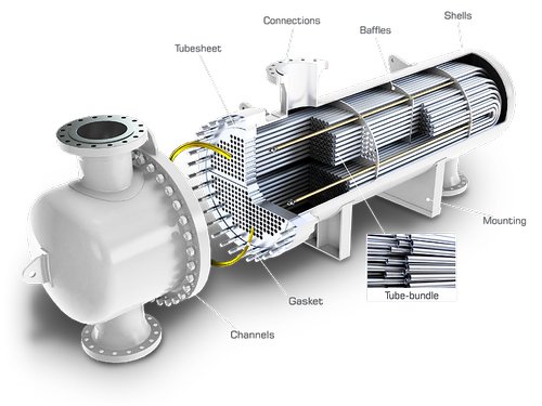
Types :
- Floating Tube-sheet Design
- Fixed Tube-sheet Design
- U-Tube Bundle Construction
Applications:
- Hydraulic Oil Cooling
- Lube Oil Cooling
- Pulp and Paper Industries
- Food Processing and Chemical Industries
- Pharmaceutical companies
- Quench Oil Cooling